ELEC271 W7-8
本博客草草创建,简陋不堪。本人才疏学浅,笔记也不过给诸君作一参考。如有疑惑/错漏/建议 还请使用这个匿名提问箱,我会一一回复。 不过现在本博客也增加了评论功能,你也可以直接在底下说。不过这个评论功能没有提醒……回复可能会不够及时。
https://www.tapechat.net/uu/5r0pL8/ZV9H0543

WEEK7: Intro to Feedback
feedback这就有点控制的味道了(@ELEC207)我们先来看看没有feedback的放大器:
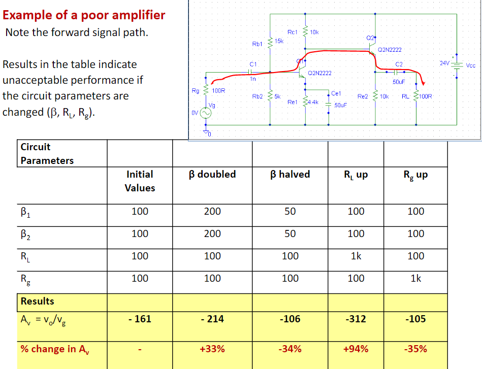
可见,三极管的 \(\beta\) , 电源电阻甚至负载电阻都会较为明显地影响放大倍数。这可不行,别的不说,负载电阻变了\(A_V\) 跟着变这是否太不稳定了点……?
于是我们加上一个feedback结构:
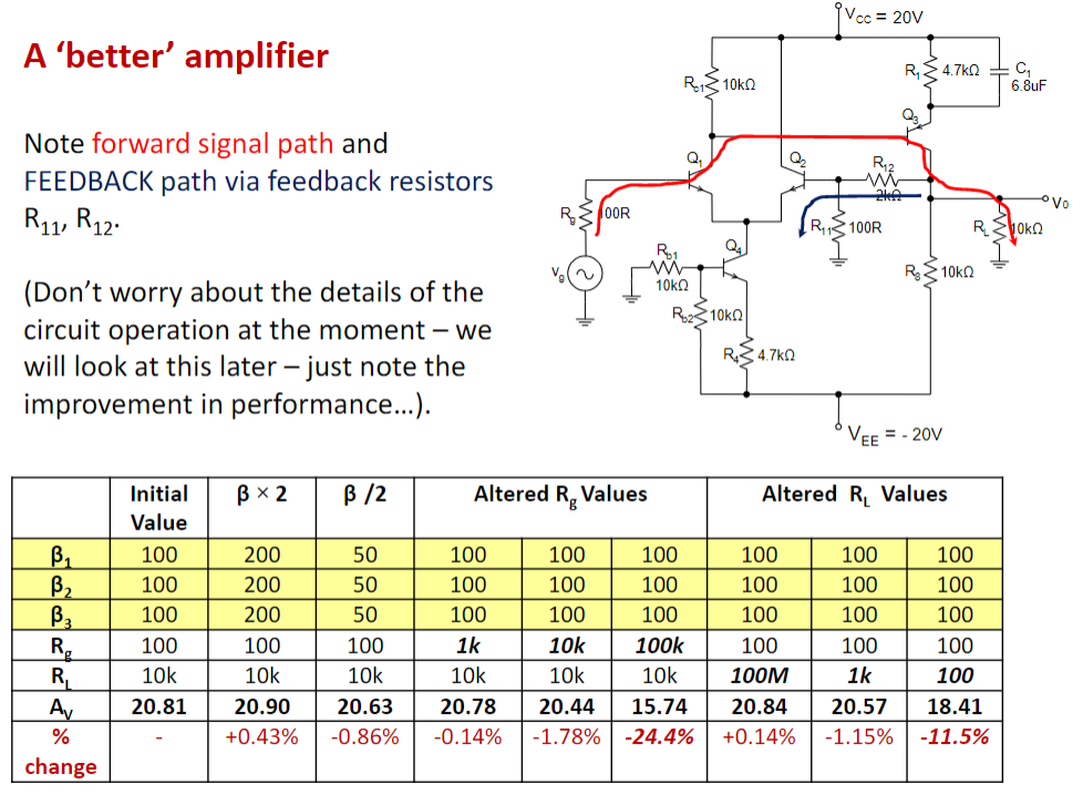
oh,much better. 虽然牺牲了放大倍数(上百 -> 20),但稳定太多了。而且,通过改变feedback结构的电阻值(R11 and R12)就能改变\(A_V\),好不方便!
Advantages of Negative Feedback
- Negative feedback reduces the sensitivity of the gain on parameters of amplifier such as transistor current gain. 降低了对晶体管参数的敏感性
- Negative feedback allows us to set gain to any value we want. 可以控制gain的值
- Negative feedback increases the bandwidth of the amplifier. 增大了放大器带宽
- Negative feedback reduces distortion. 减少了失真
- Negative feedback allows us to adjust the input and output impedances of an amplifier. 输入输出阻抗可改啦
Disadvantages of Negative Feedback
- Negative feedback always reduces the gain of an amplifier. 通常会降低gain
- Over certain frequency ranges, it can be that negative feedback changes from negative to positive with catastrophic results. Positive feedback increases gain of the amplifier and amplifier may be converted to an oscillator –no longer any use as an amplifier. 在某些频率,负反馈可能会变成正反馈,让放大器变成振荡器。
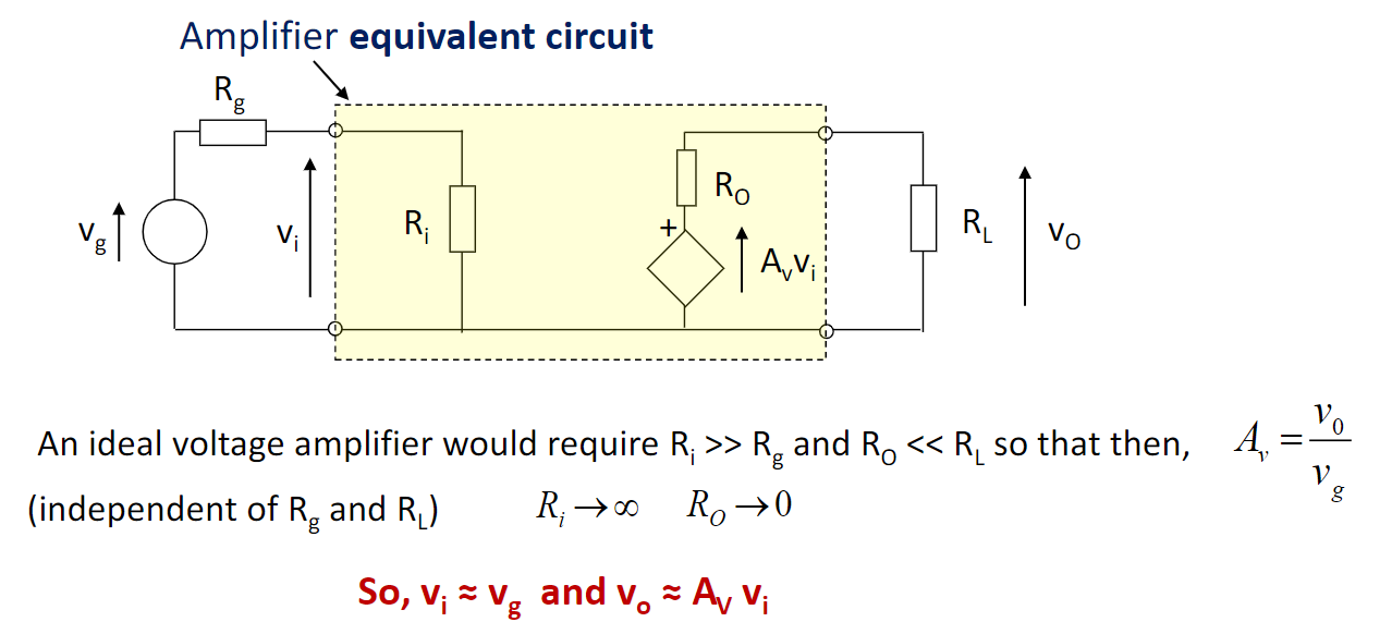
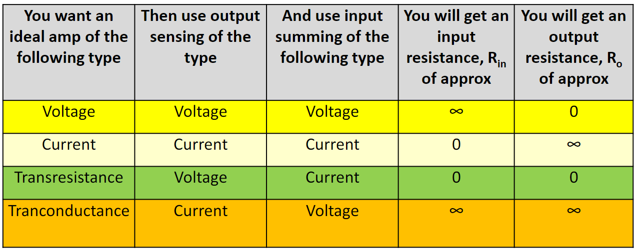
Different types of amplifier
加入feedback,要搞清楚放大器是什么类型的。
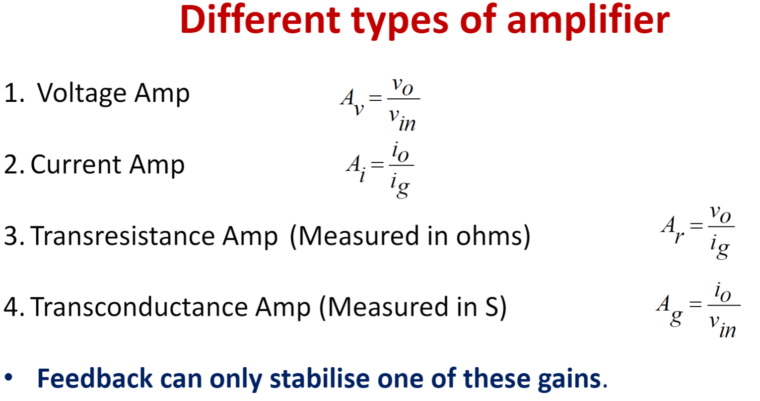
对于理想的voltage amplifier,\(R_{in}=\infty,R_{out}=0\)
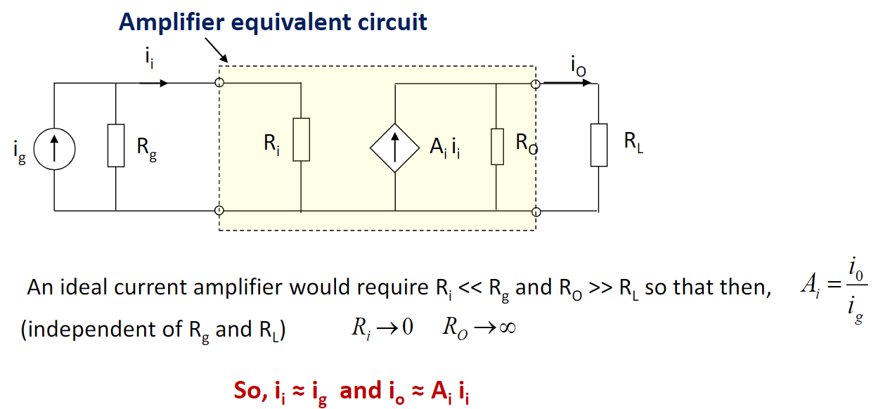
对于理想的current amplifier,\(R_{in}=0,R_{out}=\infty\)
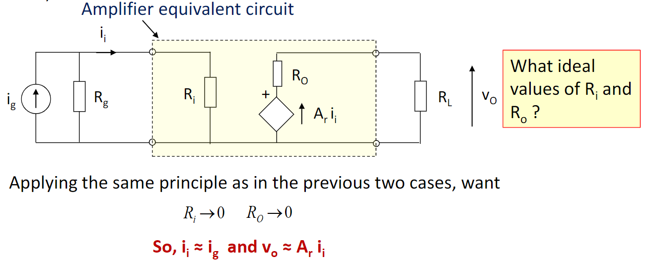
对于理想的transresistance amplifier,\(R_{in}=0,R_{out}=0\)
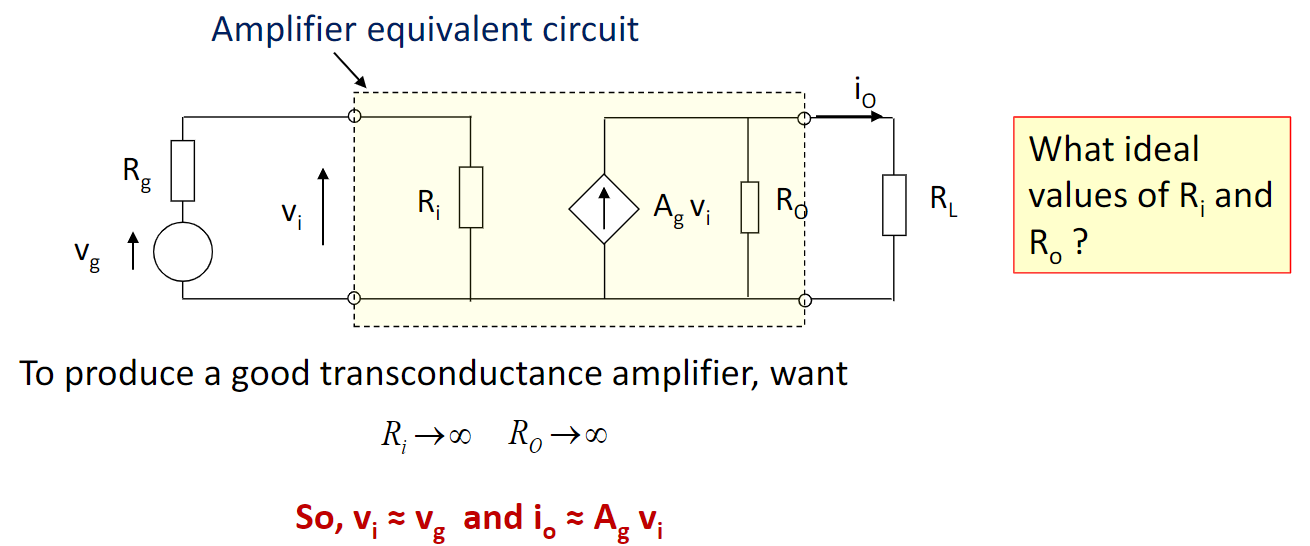
对于理想的transconductance amplifier,\(R_{in}=\infty,R_{out}=\infty\)
Output sensing & Input summing
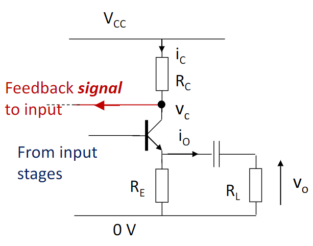
Output sensing:
- 接入点和输出直连,是为 voltage sensing,令\(R_0 \rightarrow 0\)
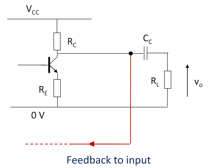
- 接入点不和输出直连,是为 current sensing,令\(R_0 \rightarrow \infty\)
Input summing
- 接入点和输入直连,是为 current summing,令\(R_i \rightarrow 0\)
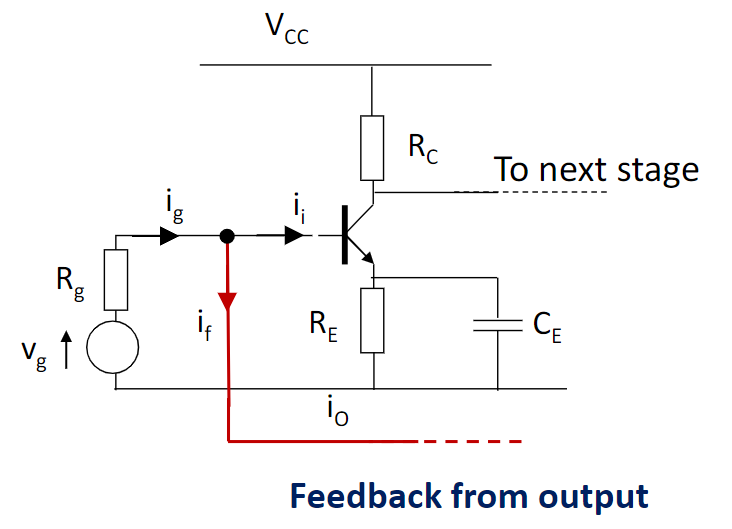
- 接入点不和输入直连,是为 voltage summing,令\(R_i \rightarrow \infty\)
sensing 和 summing 4种组合,对应4种放大器。
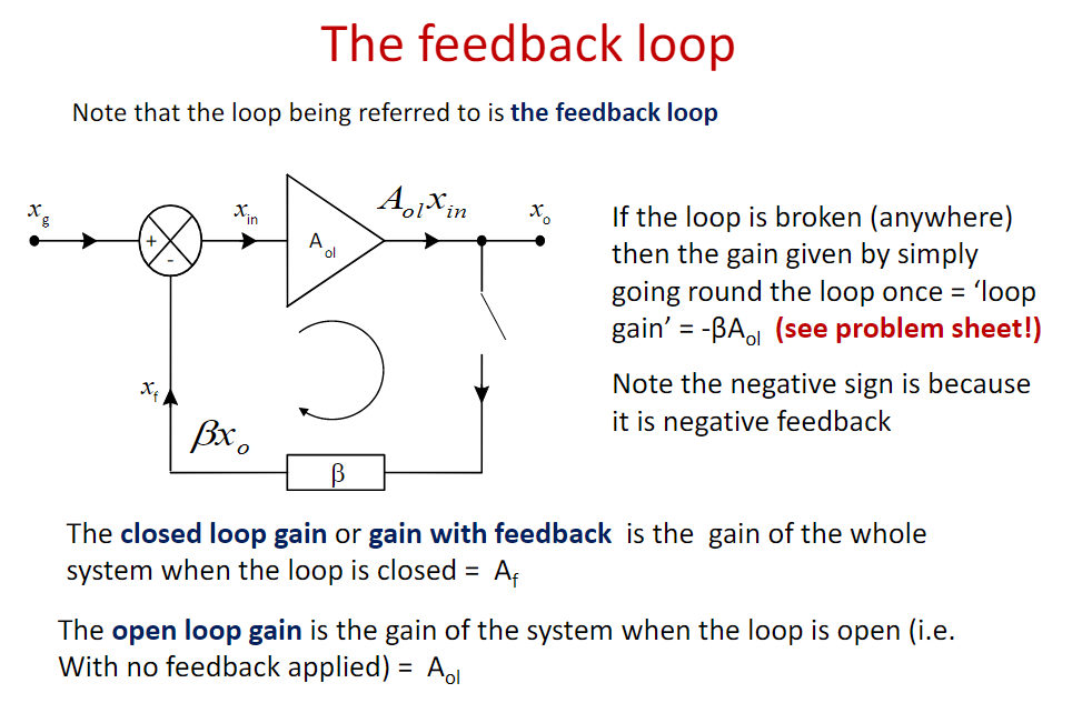
WEEK8: Feedback Theory
一旦系统地研究feedback,开环闭环是躲不开的。和ELEC207一样,我们都是一个理论。
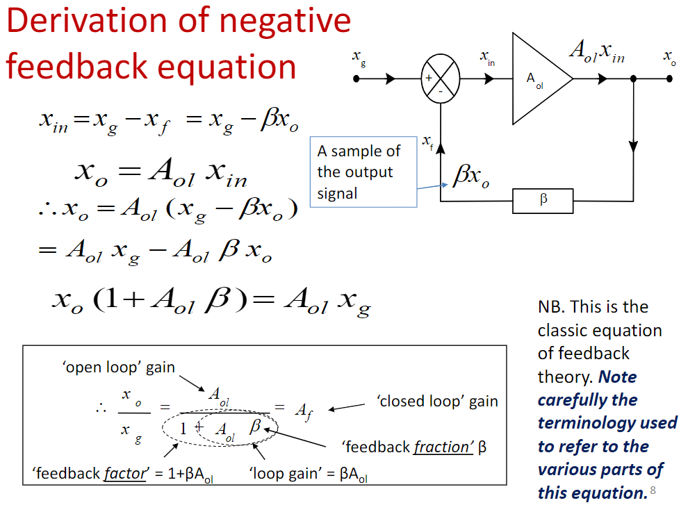
如果我们有开环增益 \(A_{ol},\) feedback系数 \(\beta,\) 则闭环增益\(A_f\)为: \[ A_{f}=\frac{A_{o l}}{1+A_{o l} \beta} \] 若\(A_{ol}\) 值有变:
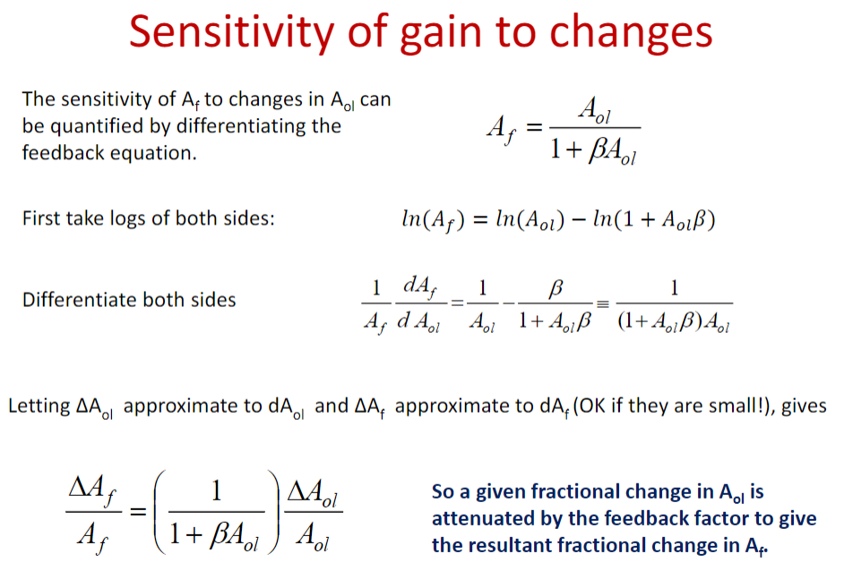
可得: \[ \frac{\Delta A_{f}}{A_{f}}=\left(\frac{1}{1+\beta A_{o l}}\right) \frac{\Delta A_{o l}}{A_{o l}} \] 这也就定量证明了为什么加上feedback后\(A_f\)会比\(A_{ol}\)稳定那么多。
更进一步,如果 \(\beta A_{o l}\) 很大,比如\(\beta A_{o l}>100\) ,则有:\(\frac{A_{o l} \beta}{1+A_{o l} \beta} \approx 1,\) 于是: \[ A_{f}=\frac{A_{o l}}{1+A_{o l} \beta}=\frac{1}{\beta} \frac{A_{o l}\beta}{1+A_{o l} \beta}\approx \frac{1}{\beta} \] 于是我们惊讶地发现:\(A_f\) 和 \(A_{ol}\) 无关了,得 \(\beta\) 者得 \(A_f\)!
apply
将这种理论用于分析放大器电路基本流程:
- 根据sensing 和 summing 组合判断放大器类型
- 化简成feedback loop 模型
- 分析电路,算出\(\beta\)
- 得 \(\beta\) 者得 \(A_f\) , 算出开环增益,结束。
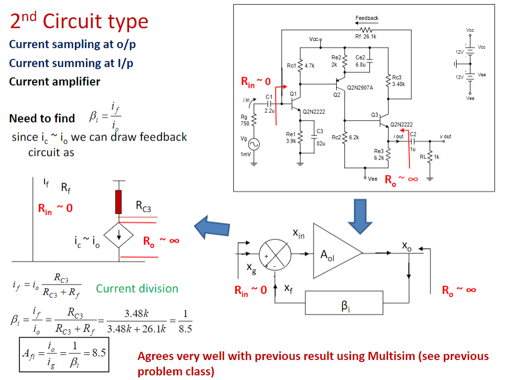
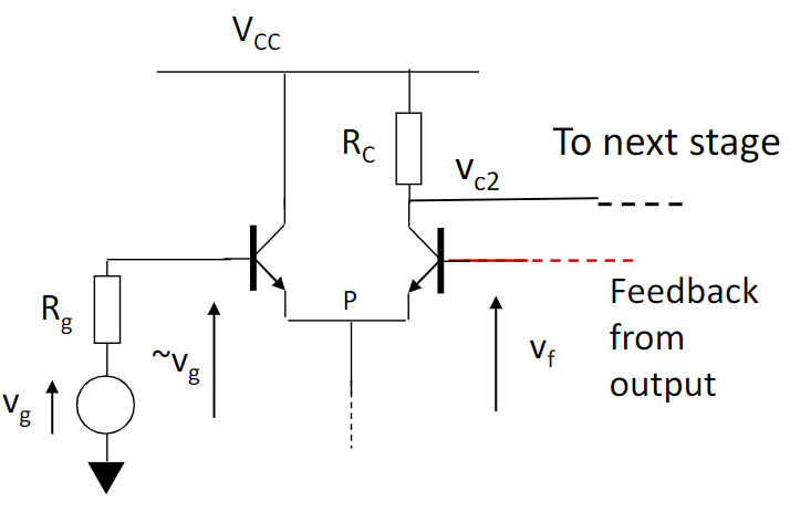
比如:
下图中,\(i_f\) 信号会从 vcc 经过 \(R_{c3}\) 和 \(R_f\) 回到 input
\(i_o\) 信号则只会从 vcc 经过 \(R_{c3}\) 和 Q3 (等效电流源) 来到 output
feedback分析中,我们将 input 和 output 视作等效,于是图中等式也呼之欲出了。