ELEC211 notes
ELEC211 notes
WEEK1
咱们第1周是一些基本的数字电路概念/模型等,约等于复习一遍EEE104。
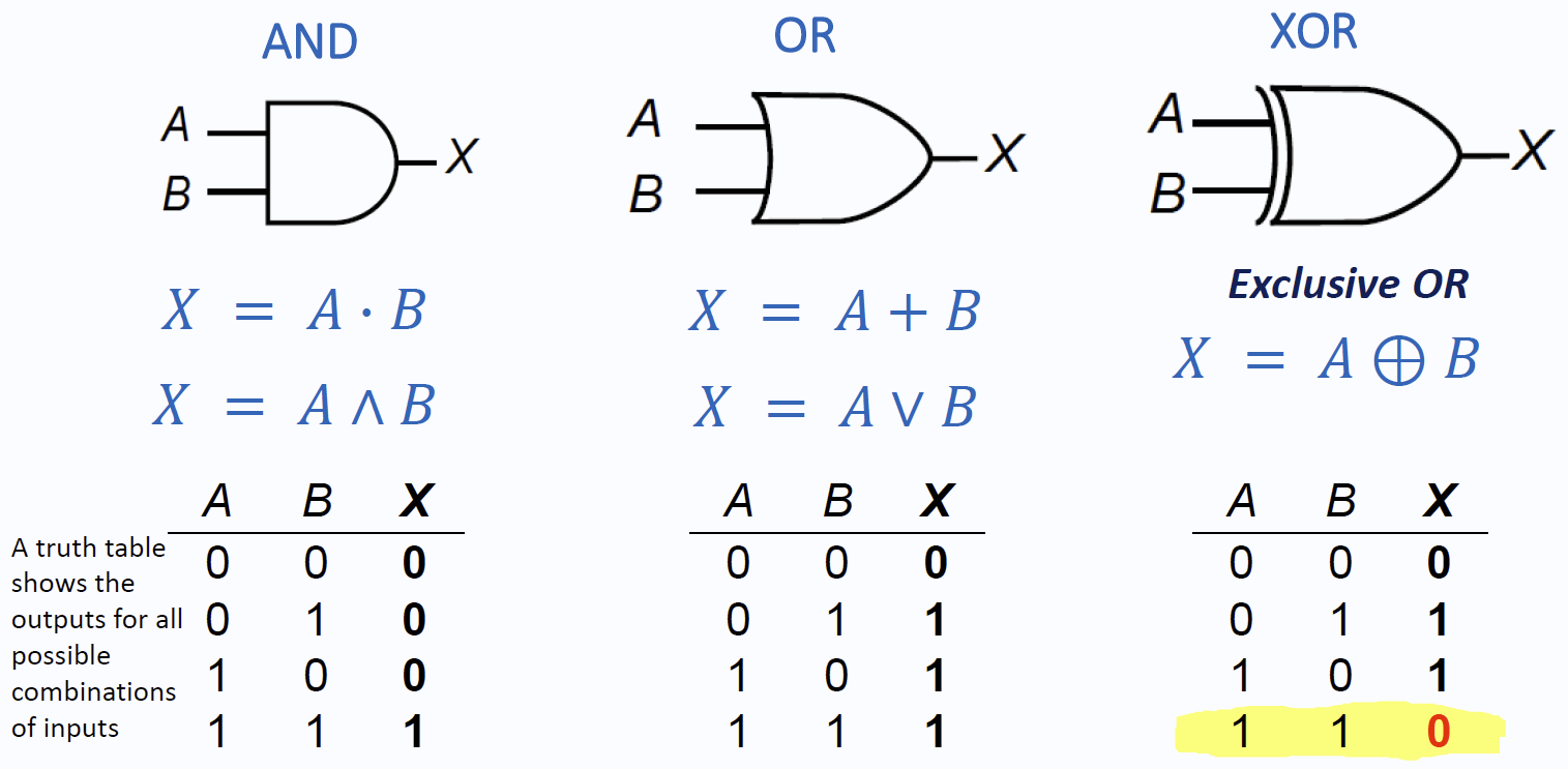
Logic gates and combinational logic
新增数学记号:
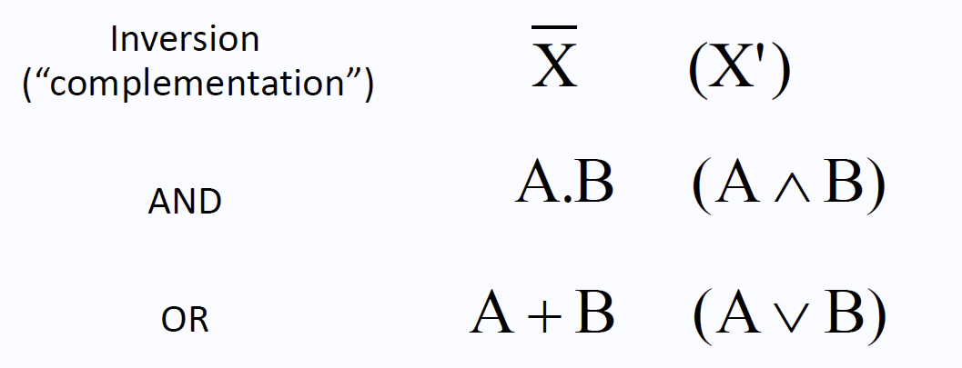
NOT gate:

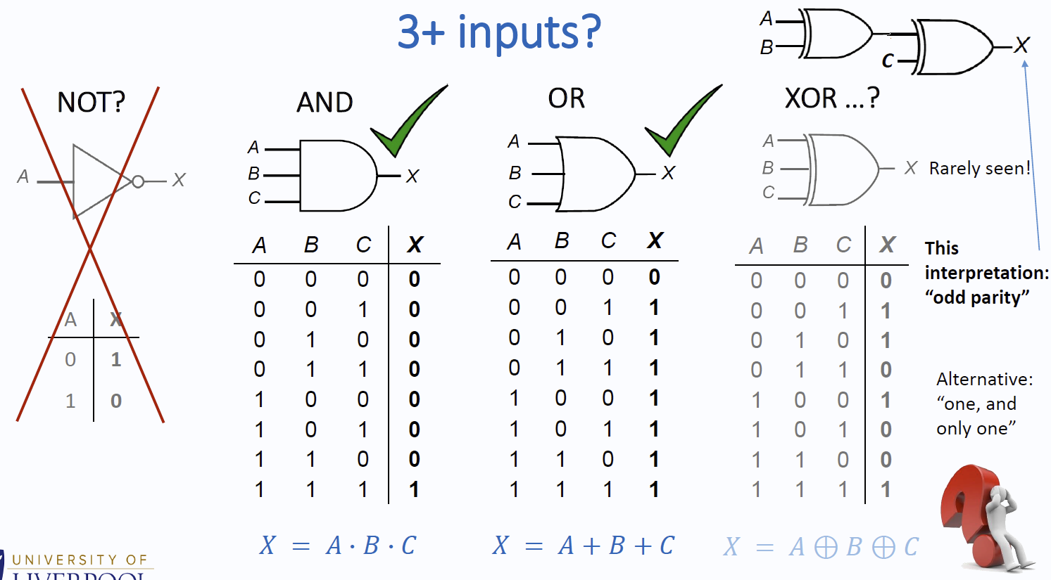
此处XOR逻辑=“取奇数输入”,少见。X = ((A XOR B) XOR C)
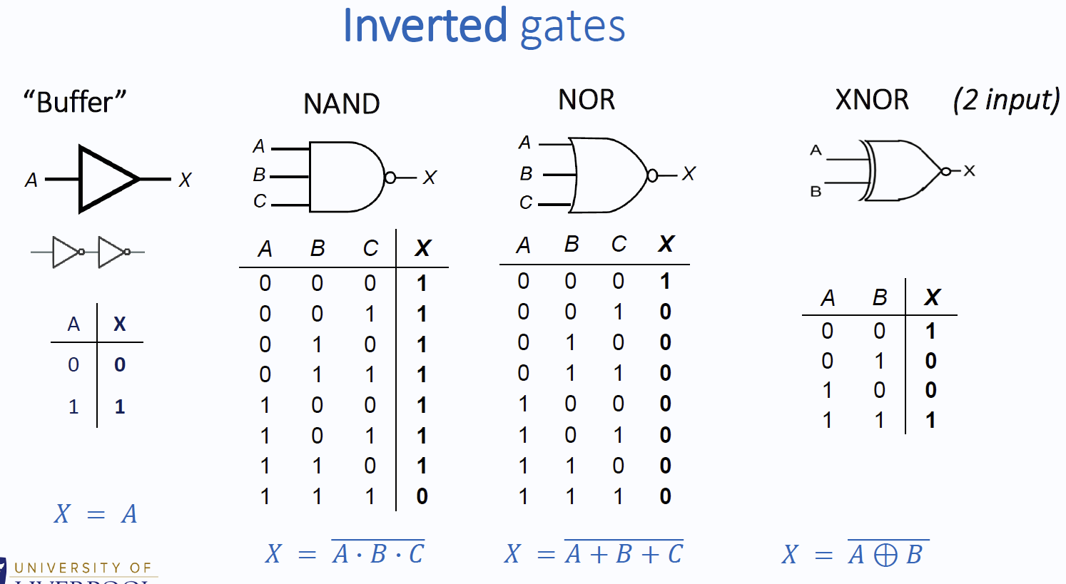
其中,NAND 和 NOR 也被称为Universal gates,因为我们可以仅使用他们中的某一种来实现所有的布尔逻辑:
NAND:
NOR:
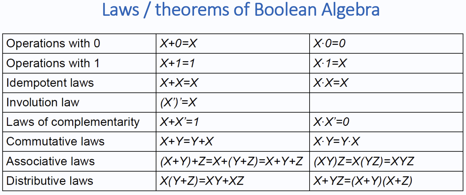
Combinational circuits 组合电路 •Present output depends only on present input •Combinational logic uses Boolean algebra:
*使用卡诺图化简通常比看这种表格来得更快。

Sequential circuits 时序电路 •Present output values depend on present and past values •Circuit ‘remembers’ its own state
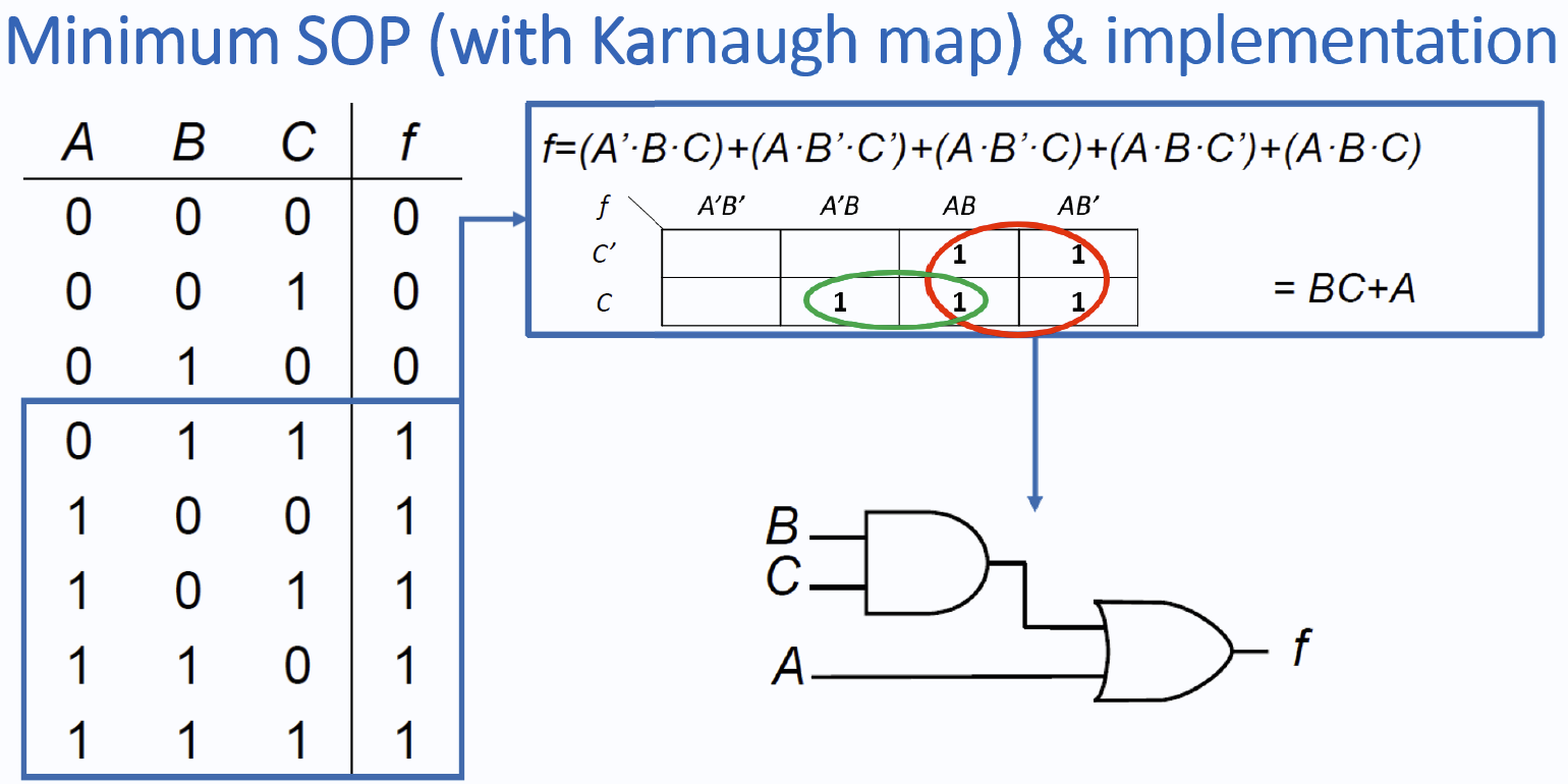
Minterms/Maxterms and implementing functions
Minterms: Sum of Products (SOP)
Maxterms: Product of Sums (POS)`
implementing
functions: 大概就是这个意思,不如卡诺图。
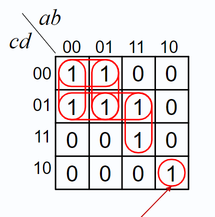
Karnaugh maps
一图足矣!
A little on decoders
Multiplexer 数据选择器/多路开关
A multiplexer在多个输入中,依据数个控制用输入(control inputs)选择一个作为输出。(下图右)
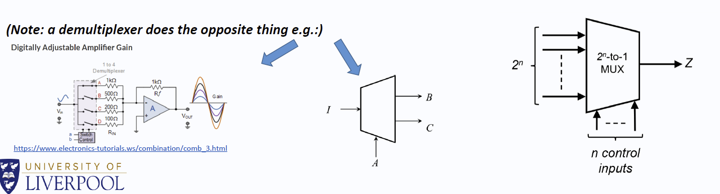
A multiplexer has: •At least two inputs •One or more control (select) inputs •One output
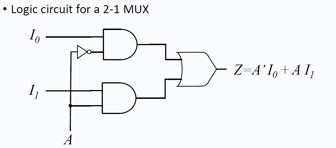
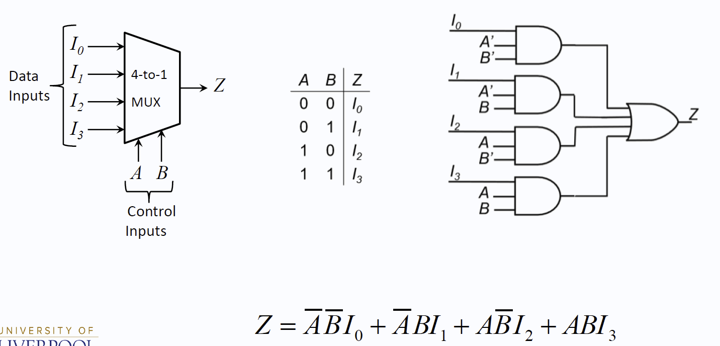
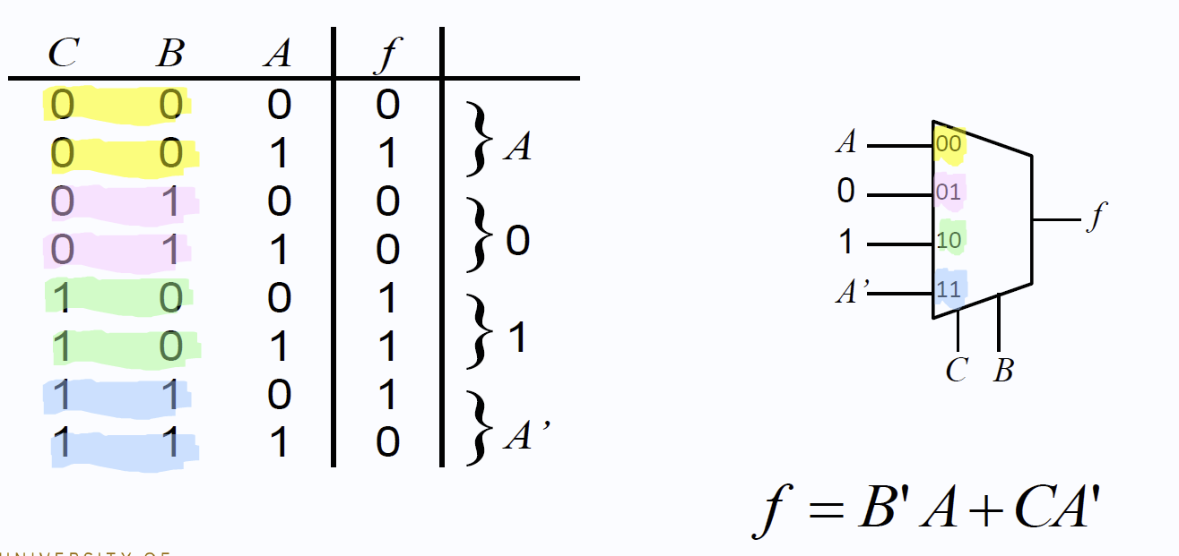
实现:
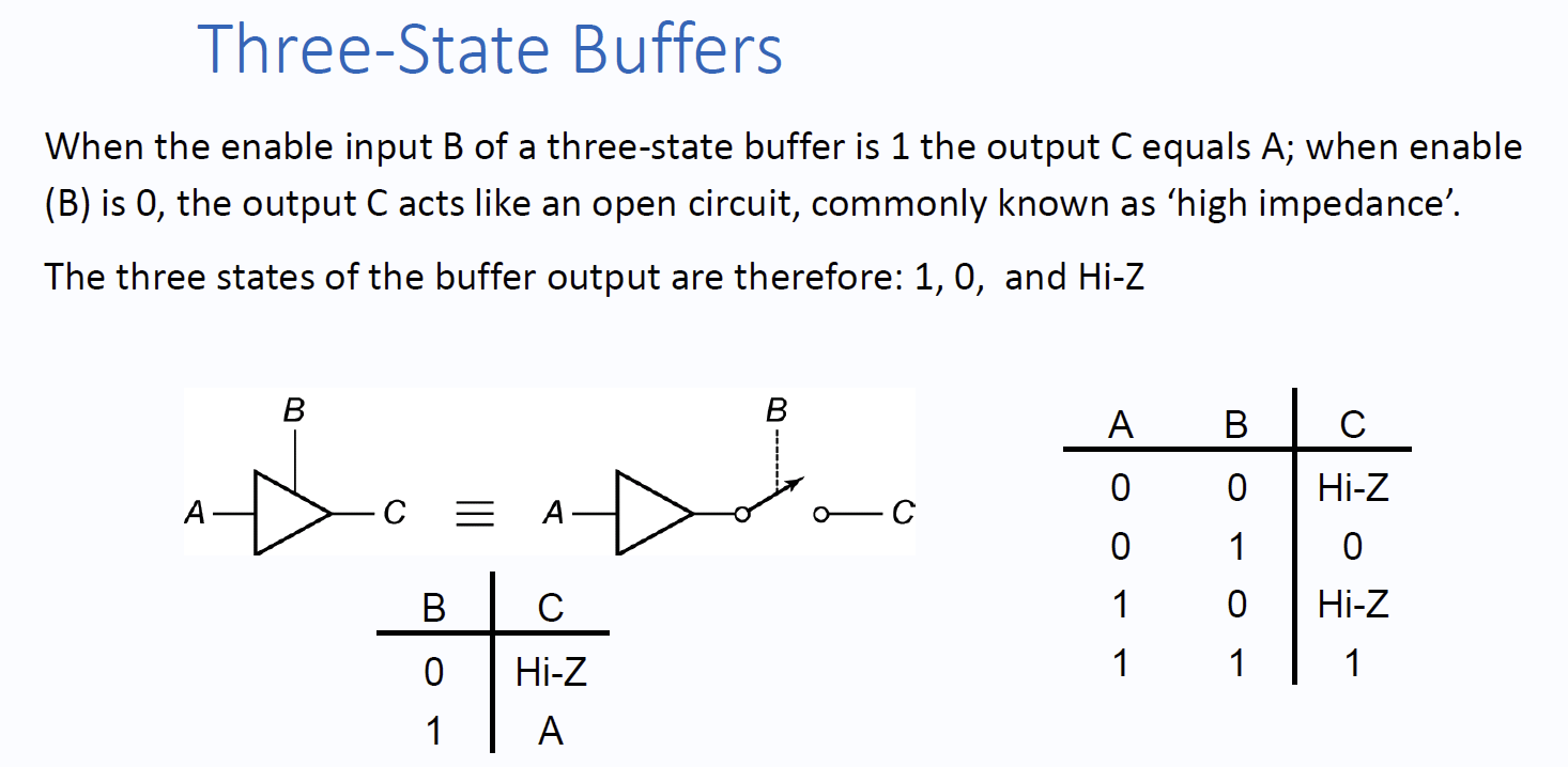
Tristate gates 三态门(three state buffers)
States of Tristate gates:
1,0, high impedance (Hi-Z) 高阻抗 (断路
why?
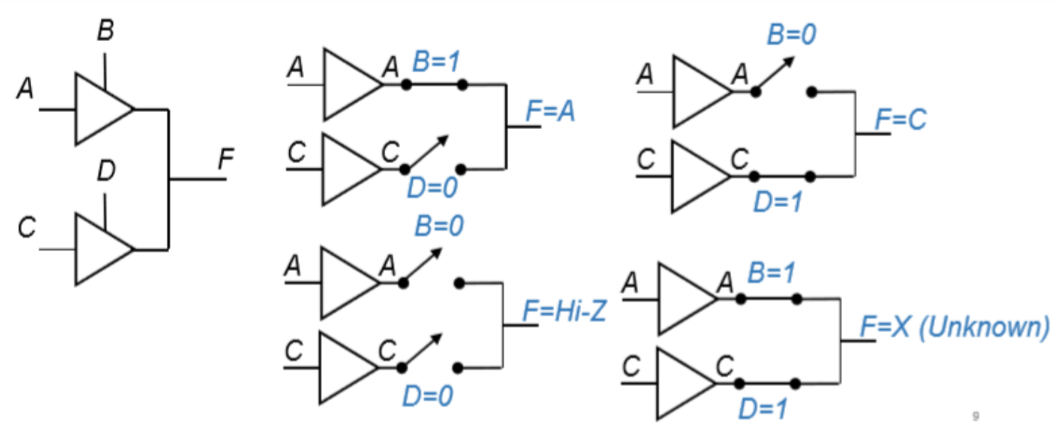
当多个逻辑电路的输出合并到一条线上,他们的输出会产生冲突:同时短接高低电平,你到底算哪个呢?
此时,Hi-Z提供了解决冲突的方法:多了一种输出——断路。这就意味着,在多个输出里,如果只有一个具有0/1输出而其它都断路的话,那么总输出就必然与0/1输出一致。
实现:
典中典4种情况:
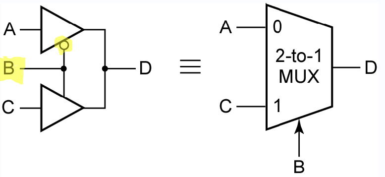
某种意义上起到了 multiplexer 的作用。
list of test in week 11
------------------------Digital Electronics------------------------
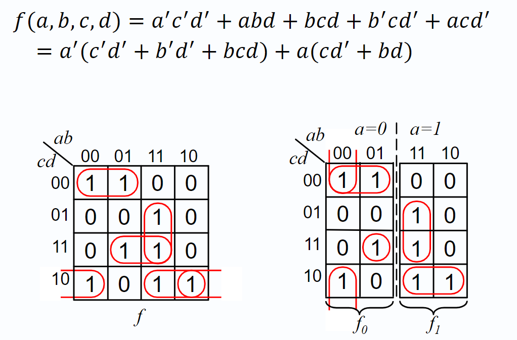
Shannon’s Expansion
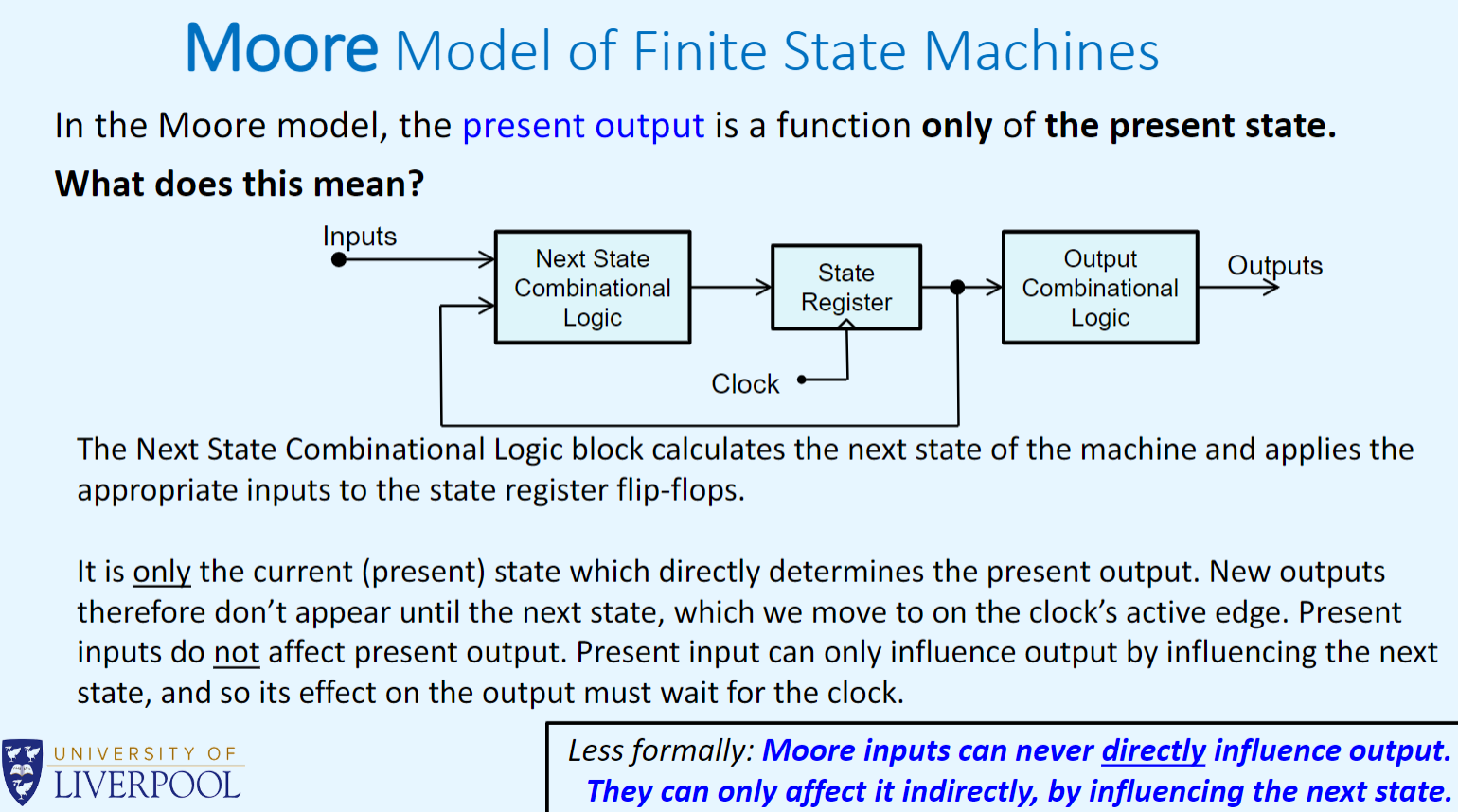
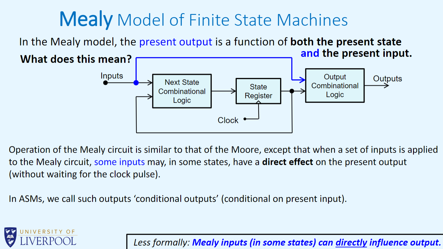
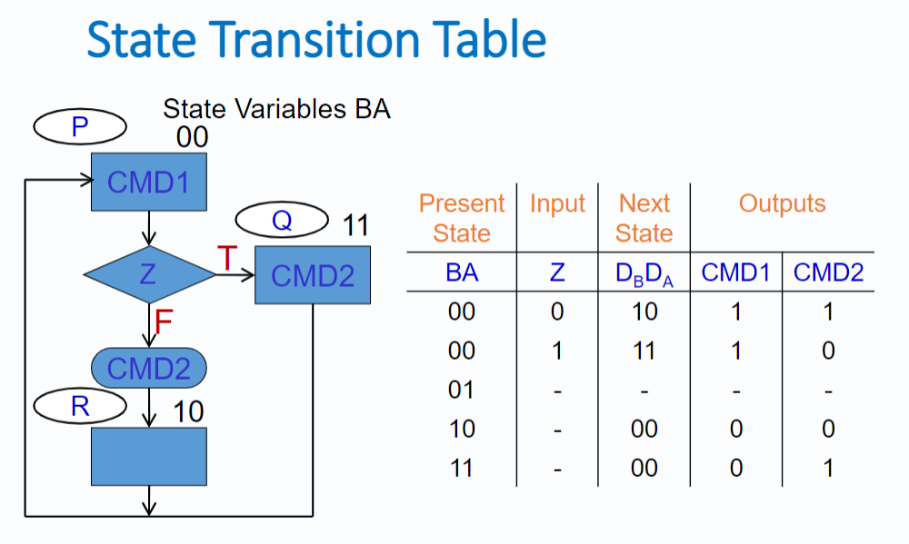
Mealy / Moore machines
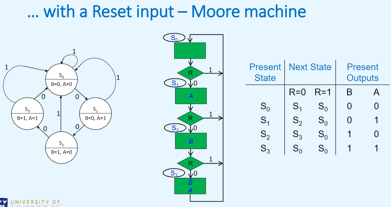
In Moore machines, output=f(current state)
In Mealy machines, output=f(current state, input)
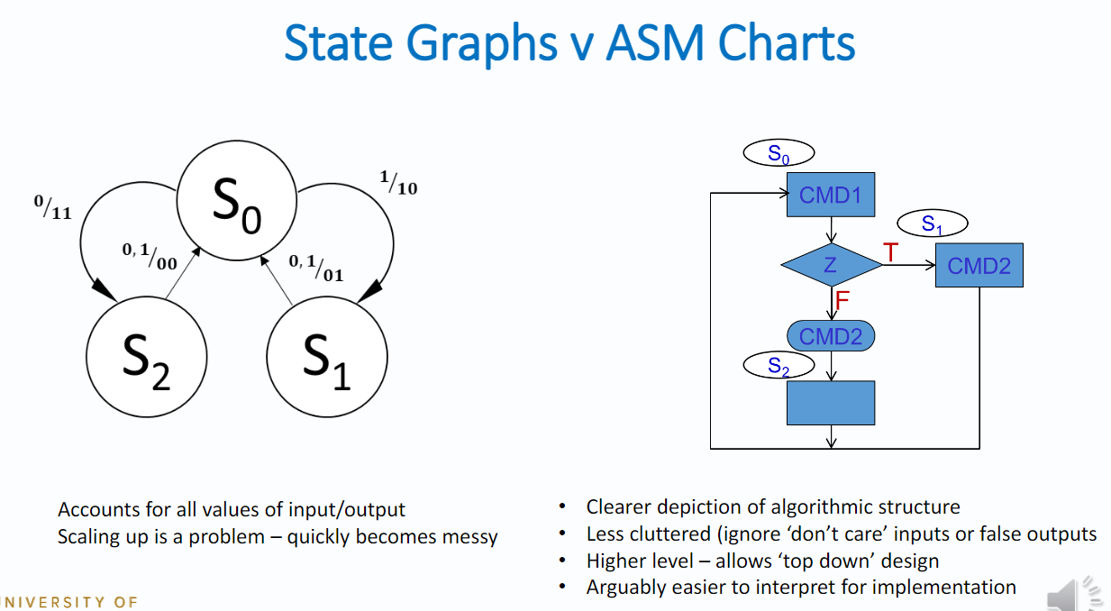
ASM Design techniques
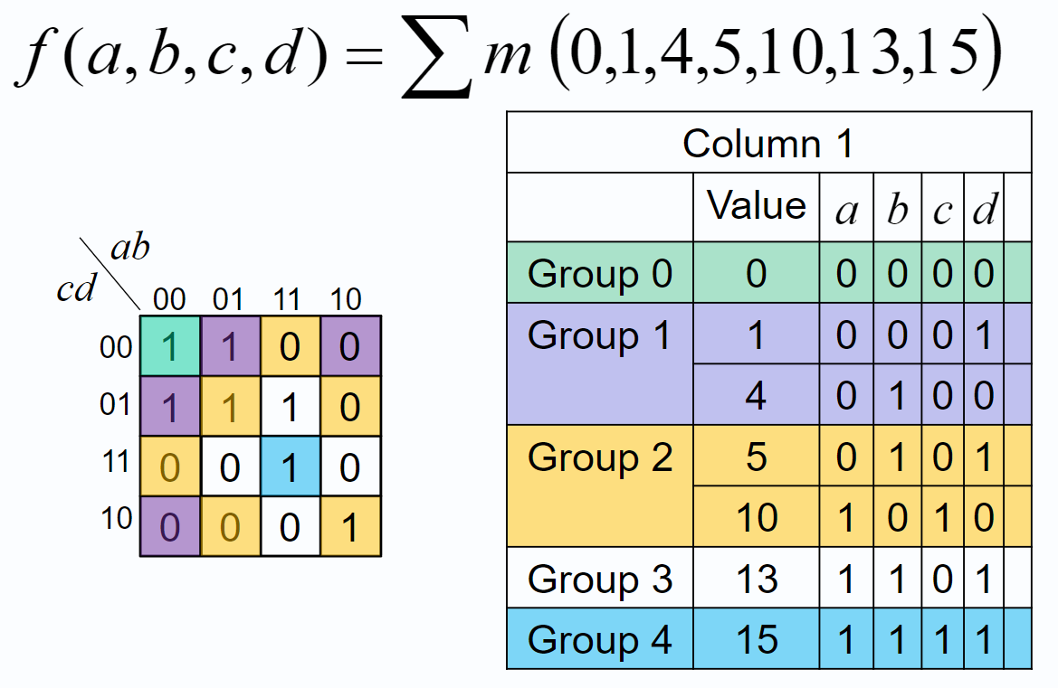
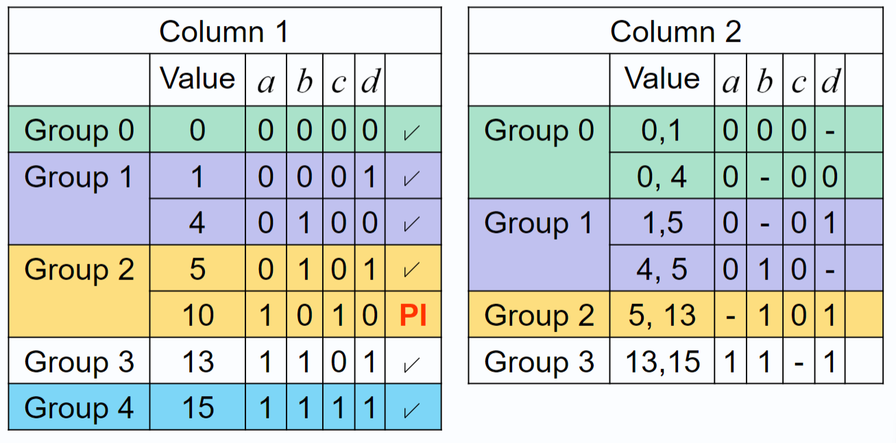
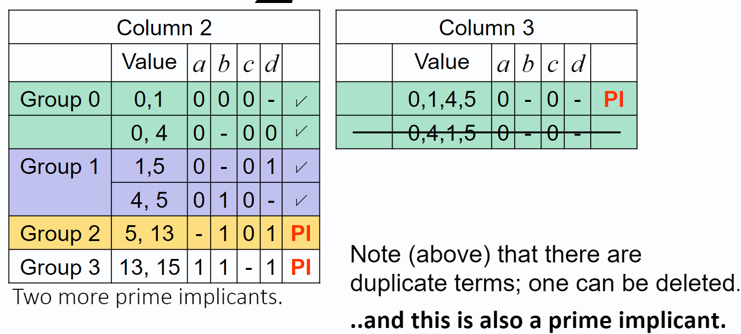
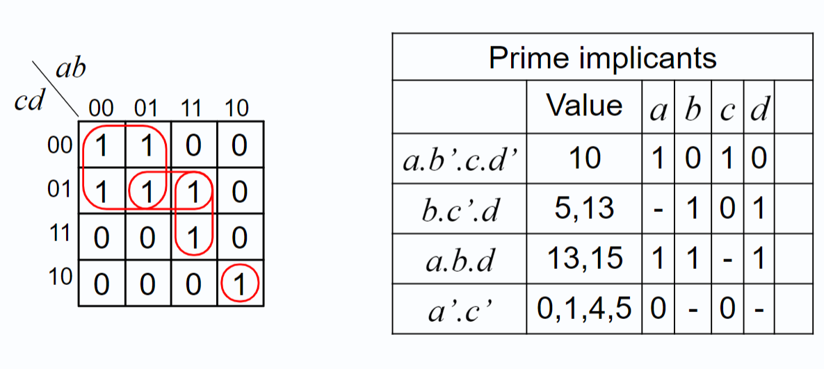
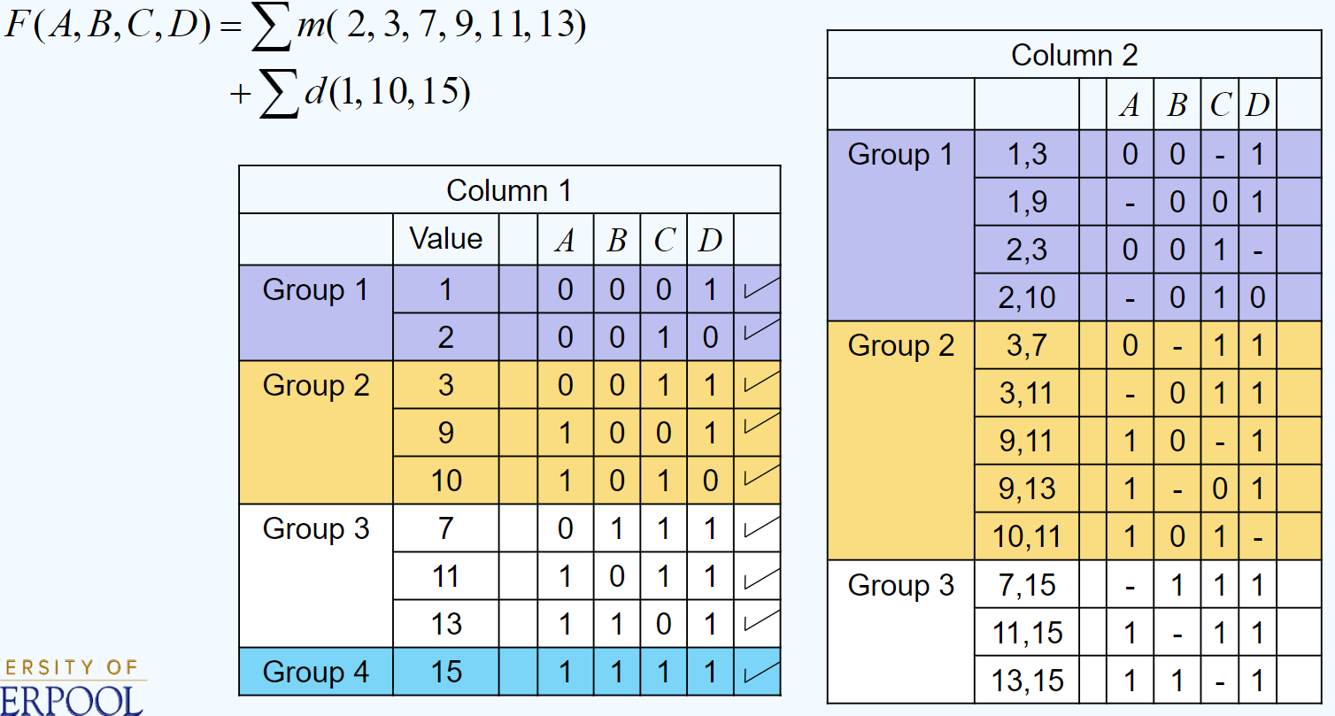
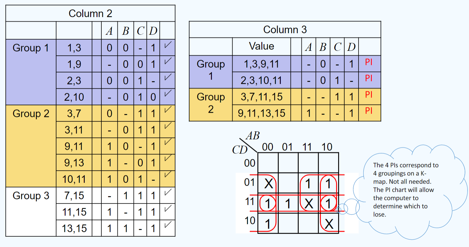
Quine-McCluskey v Karnaugh
Incompletely Specified Functions
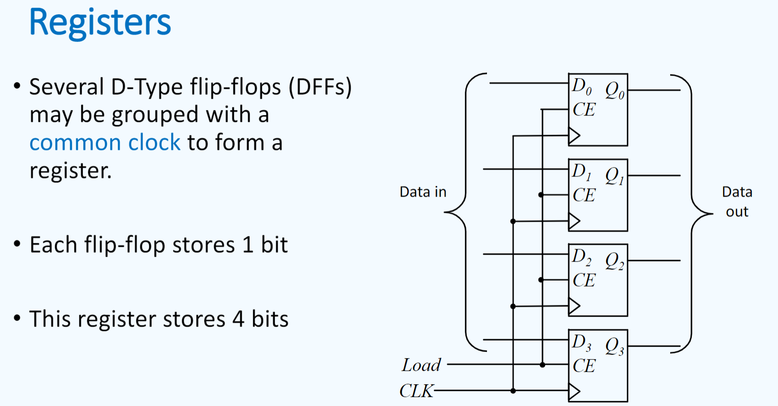
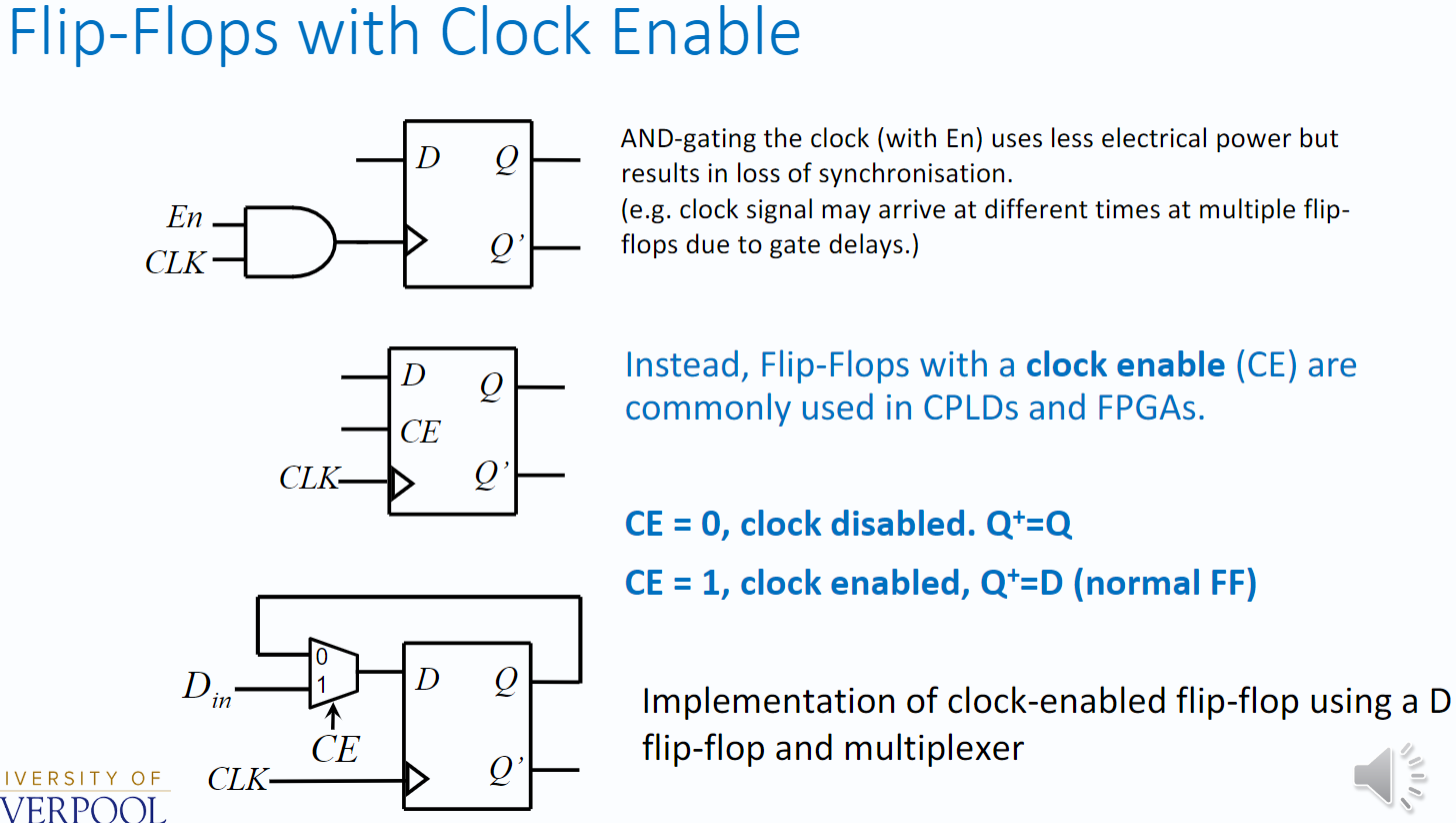
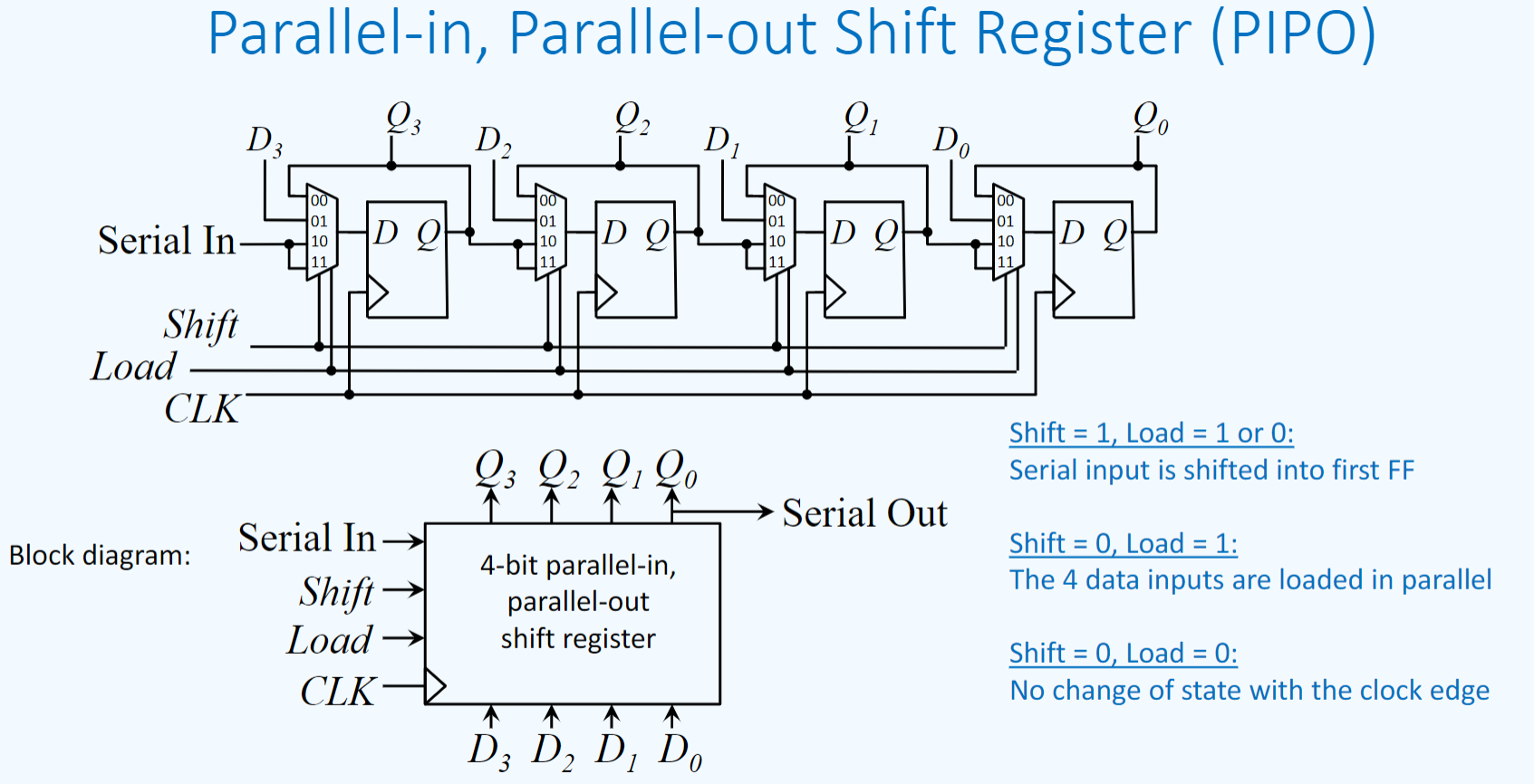
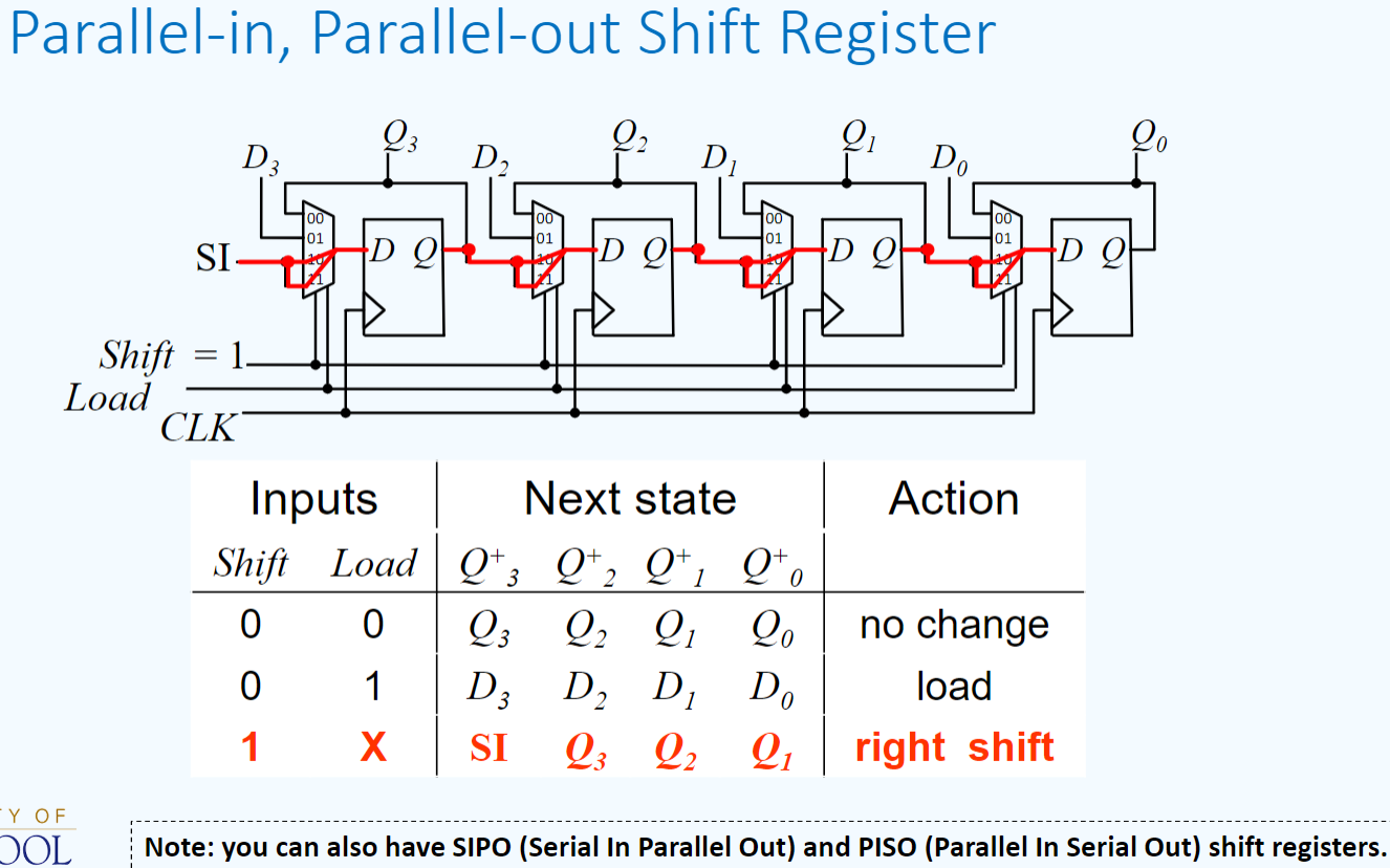
Registers
use D Flip-Flops with Clock Enable
When Load is 1 the clock is enabled (CE) and the data applied to the D inputs will be loaded into the flip-flops.
When Load is 0 the register holds its data (memory).
D Flip-Flop
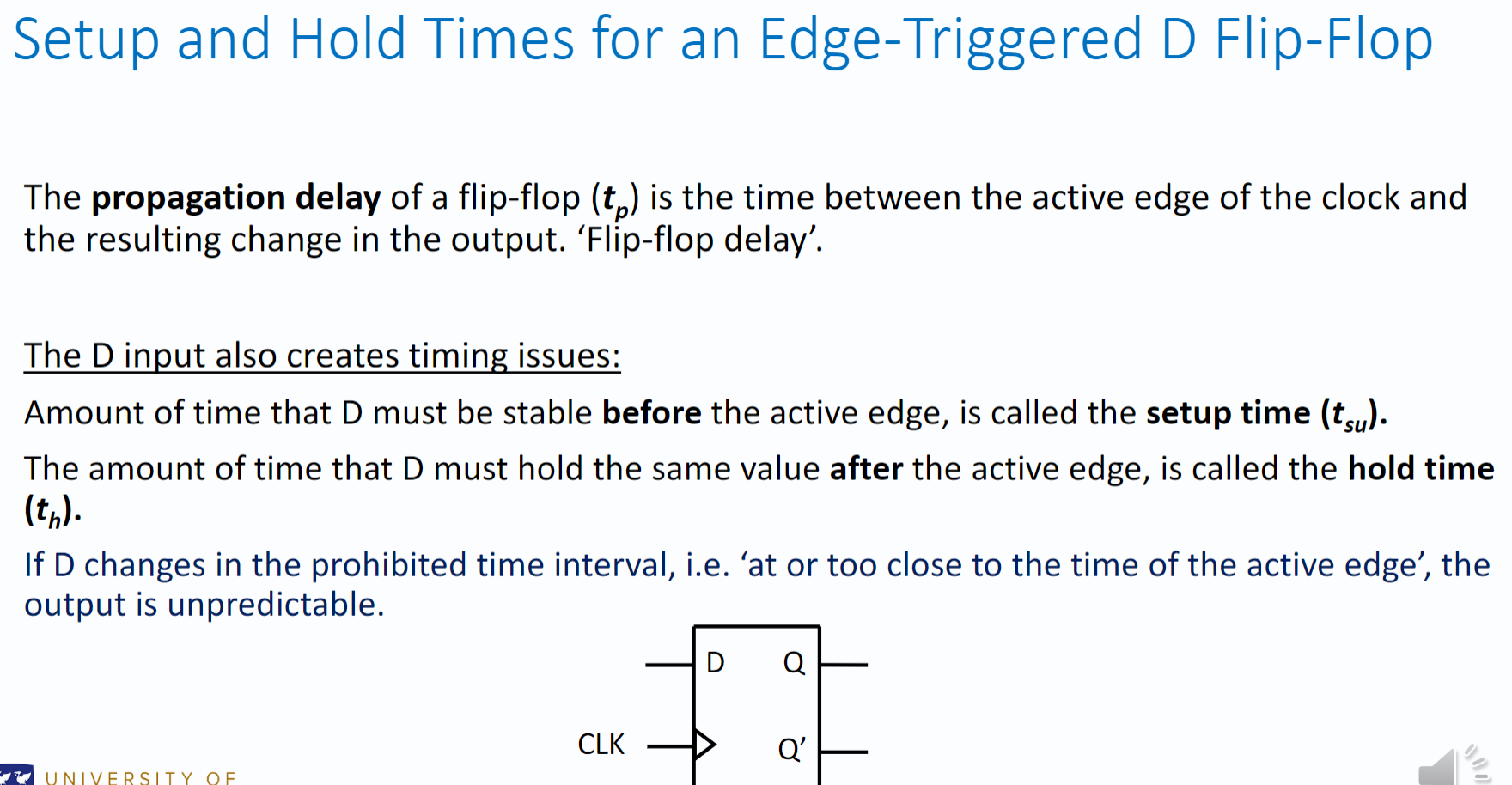
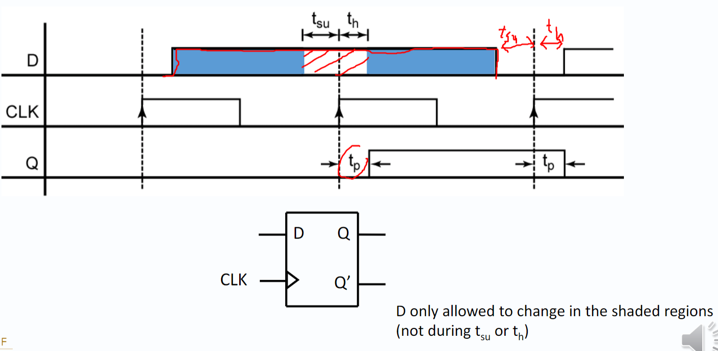
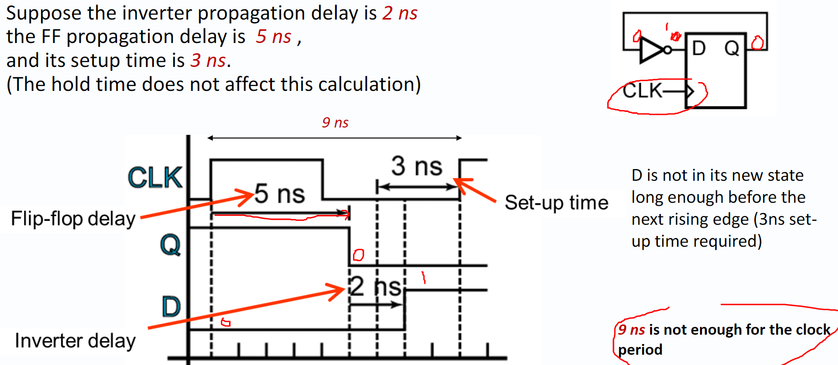
Minimum Clock Period = flip-flop propagation delay + setup time + propagation delay of other components in circuit
Serial data transmission and Registers
Registers
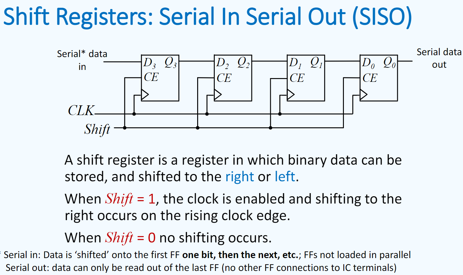
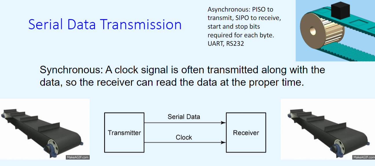
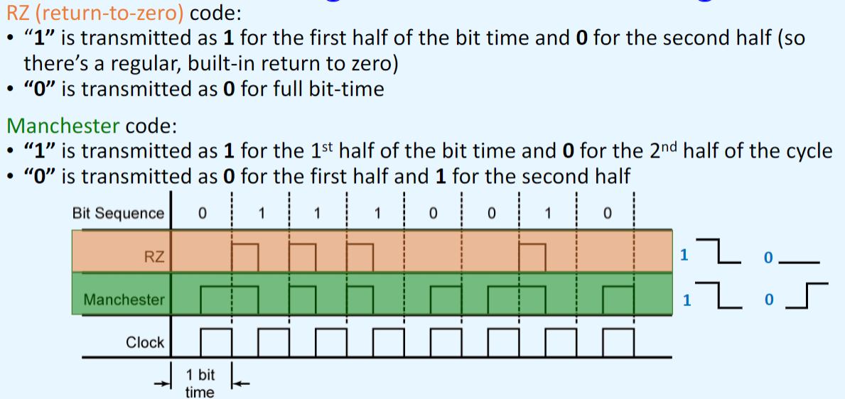
Serial data transmission
或者
具体传输编码
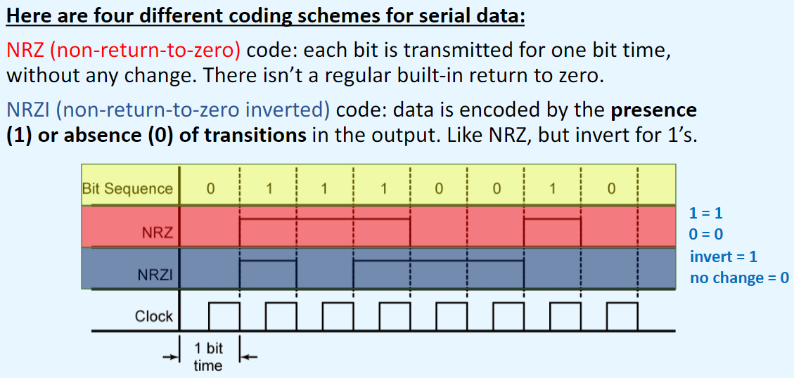
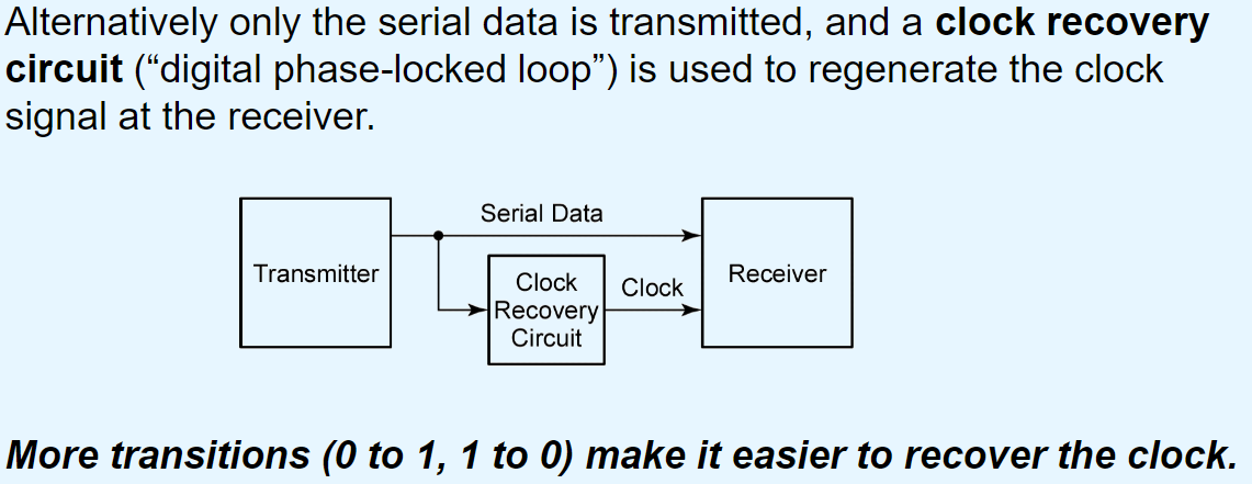
“self-clocking” signals:
------------------------Microprocessor Systems------------------------
Shift-register
LSLS - logical shift left: abcdefghijkl => defghijkl000
LSRS - logical shift right: abcdefghijkl => 000abcdefghi
ASRS - Arithmetic shift right: abcdefghijkl => aaaabcdefghi *a是符号位
PORS - Rotate right: abcdefghijkl => jklabcdefghi
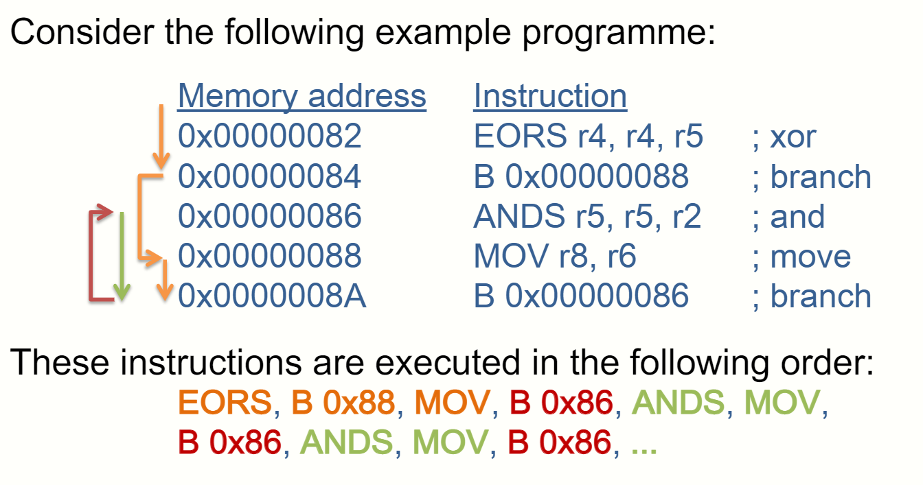
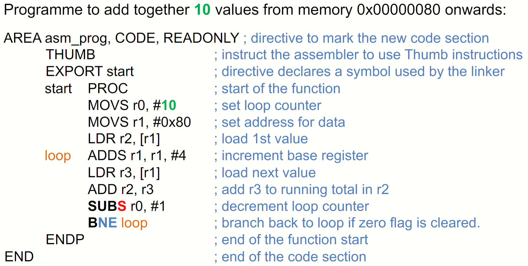
Branch
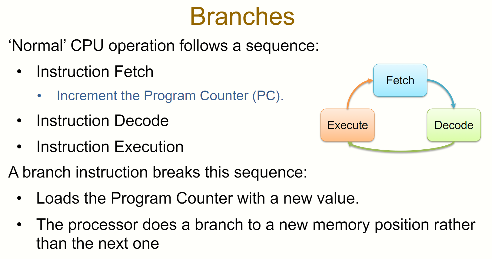
B
B<cond>
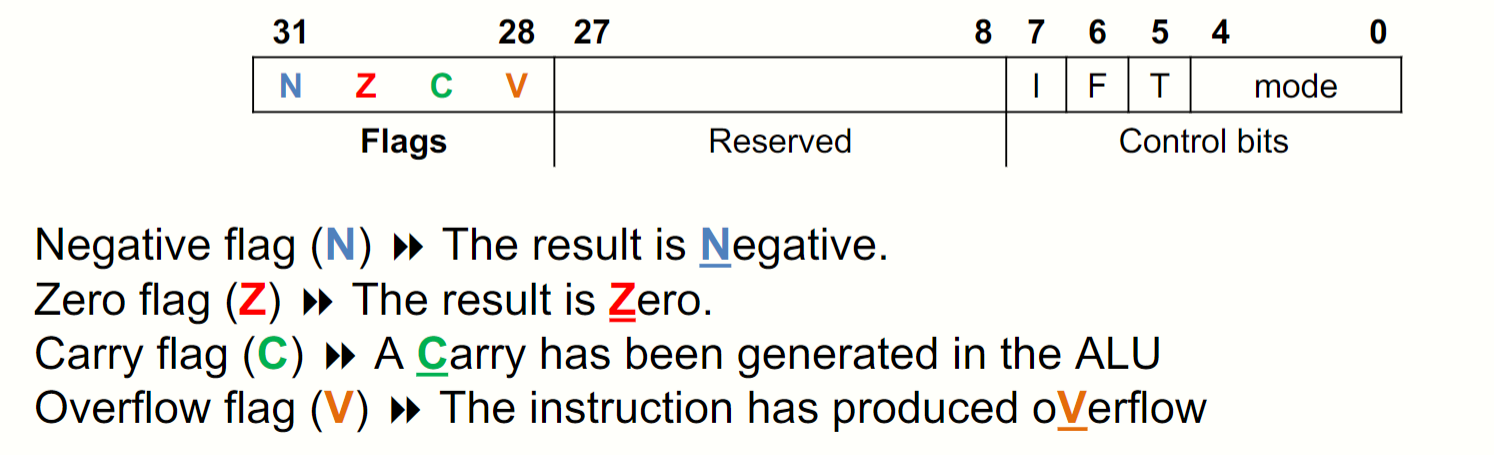
Flags
注意, 当运算的结果产生进位或者减法运算没有借位的话C=1,其他情况C=0
Negative numbers
0……
1……
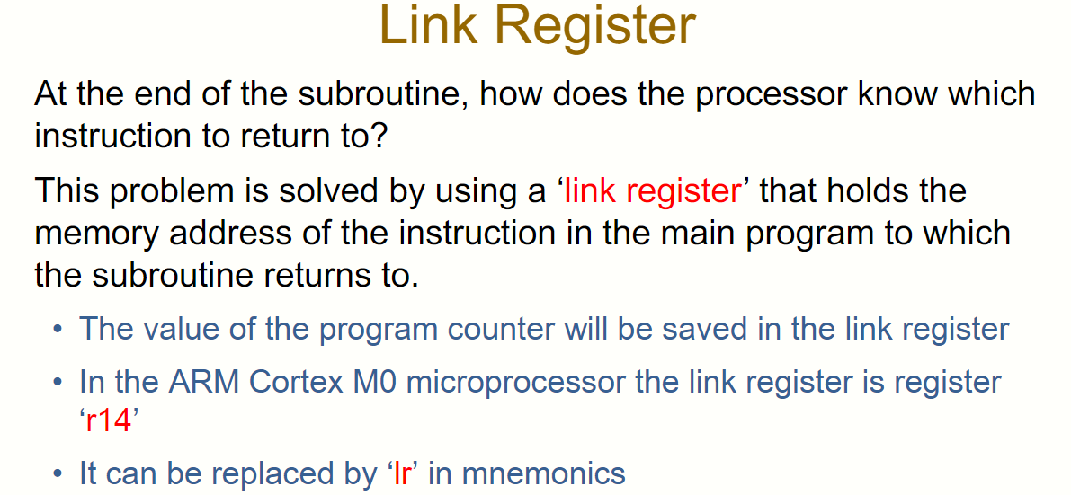
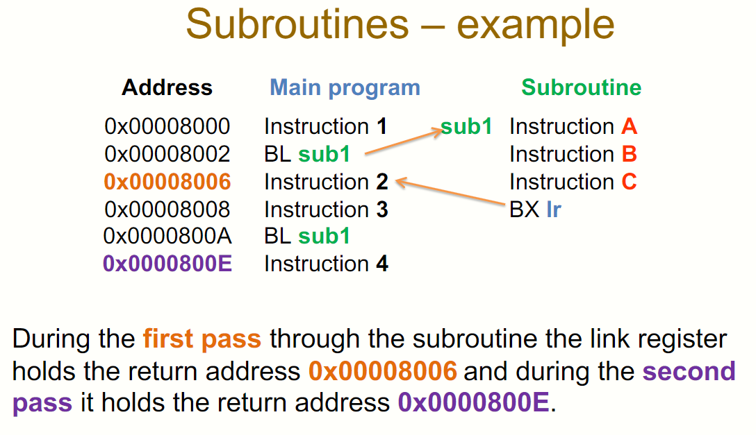
PC vs LR
PC: program counter
PC中存放下一次访存的地址。
LR: link register
函数的返回地址
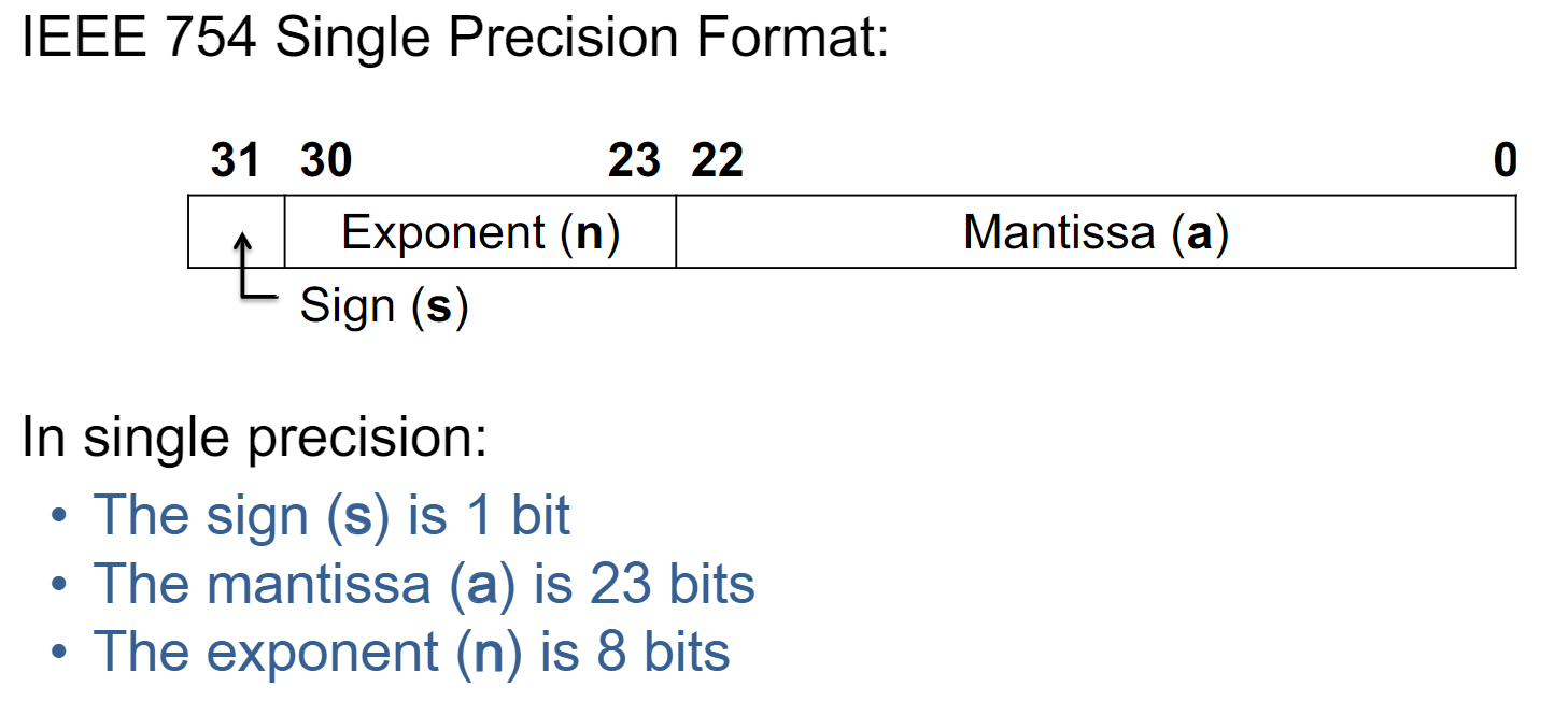
IEEE754 standard
Carry vs Overflow
carry: 无符号溢出
Overflow:有符号溢出